Introduction
I2C (or Inter-Integrated Circuit) is a pretty neat communications protocol. It needs only two wires (plus ground!), it’s synchronous, it supports multiple masters and slaves, and it’s fairly straight-forward to implement without relying on dedicated microcontroller hardware. Lately I’ve been taking advantage of that last advantage: implementing I2C on a microcontroller using software, a.k.a. bit-banging.
The need for bit-banging arises when, as mentioned, the microcontroller you’re working with has no dedicated I2C hardware or said hardware is in use with other pin functions. For example, I’ve been using the PIC16LF18323 as the Tx controller in the musicFromMotion project which has a Master Synchronous Serial Port (MSSP) module, which can operate in either I2C or SPI mode. Though SPI is typically simpler to bit-bang (especially in master mode) it can take a toll on the data rate, which was more important in my application. Thus I can use the dedicated MSSP for SPI, then bit-bang I2C on any two free GPIO pins.
(Note: some devices such as the PIC16F18323 that I’m using have a neat feature called Peripheral Pin Select where we can route the hardware I2C pins pretty much anywhere else on the chip. And then we could switch the master synchronous serial port (MSSP) between SPI and I2C to speak to the appropriate devices. But this is a special case — often we’ll be stuck with the pin functions we’re provided.)
Like any good brick-layer, we’ll start from the ground up. First, we’ll enjoy a quick tutorial on the I2C protocol in Softwareland and Hardwareland; next, we’ll lay out basic input/output (I/O) functions followed by basic I2C functions. In Part II we’ll use these basic functions to speak with an example device — an MMA8653 accelerometer — and look to where we can go next. In later posts we’ll explore some troubleshooting techniques, and even develop a debugging project! Joy!
I2C Protocol
Here’s a conversation between me and my boss:
“Initiate conversation. Calvin, I want to give you orders,” says he.
“Acknowledged,” I reply.
“Clean your desk.”
“Gotcha.”
“End conversation.”
Simple enough, yeah? We’ve just witnessed an I2C transaction! First, my boss (the ‘master’) initiates the conversation and addresses me (the ‘slave’). I acknowledge, he gives me a command. I acknowledge, he ends the conversation. This describes an I2C send byte function, and it’s one of the simplest I2C transactions there is. We commonly use such a function for basic, no-response transactions such as clearing faults or setting modes on the slave device.
For a bit more complexity, we can simply repeat the command-acknowledge lines to form an I2C send byte data function:
“Initiate conversation. Calvin, I want to give you orders,” says he.
“Okay then,” I reply.
“That desk cleaning project I have you on.”
“Yes.”
“Put all of your pens in the blue jar.”
“Will do.”
“End conversation.”
Here my boss is initiating the conversation, addressing me, and I acknowledge just like before. But then he gives me a context — a register or command code — and I acknowledge, then he gives me a command related to that context (data), I acknowledge, and he ends the conversation. This kind of transaction is used more frequently than plain old send byte since most devices have multiple memory registers that need to be addressed before a command can be executed.
Now if my boss ever tires of giving me orders and wants my input, things get a bit trickier. Since he’s the master, I can only speak when he requests information (life is tough for integrated circuits). So the most basic way to answer his request is via I2C receive byte:
“Initiate conversation. Calvin, I want to give you orders,” he orders.
“Surely,” I say.
“I am interested in the color pens in that blue jar.”
“Right-o.”
“Re-initiate conversation. Calvin, I want you to tell me.”
“Red.”
“Not acknowledged. End conversation.”
Now in English this sounds pretty silly, but this is the world of I2C. The first two lines are the usual, but then my boss gives me context of what he wants from me (pens in the blue jar). I acknowledge, but don’t tell him anything yet. He then re-initiates the conversation (called a repeated start condition) and addresses me with a request for information. I give it to him, he not-acknowledges me (how rude!) and ends the conversation. Such a transaction is used to receive data from, say, a sensor, or to peek into the device’s configuration. Extending to receiving multiple bytes (here ‘Red’ is one byte) requires the master to acknowledge after the first byte is received, and every byte received thereafter, until the last byte received when the master finally not-acknowledges and ends the conversation.
Translating these conversations to I2C jargon, these ‘initiate’ and ‘end conversation’ sentences represent start and stop conditions, typically abbreviated as S and P or ST and SP, respectively. The funky ‘re-initiate conversation’ is called a repeated start (RS or SR) condition and is functionally no different than a start condition, but its place in the transaction lends it its name. Acknowledges (‘right-o,’ ‘surely,’ ‘gotcha’) and not-acknowledges are abbreviated as ACK and NAK or A and N, respectively. My name is an address, and the ‘give you orders’ versus ‘tell me things’ represent write (W) and read (R) commands. Below is a nice visual reference for these transactions, courtesy of NXP:
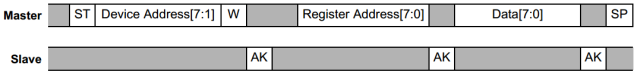
Figure 1: writing one byte of data for a register (courtesy of NXP).

Figure 2: writing multiple bytes of data for a register (courtesy of NXP).
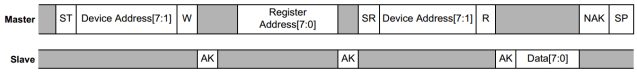
Figure 3: reading one byte of data for a register (courtesy of NXP).
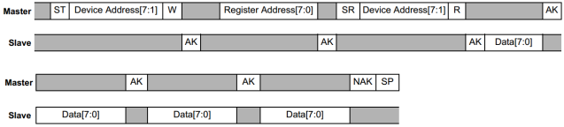
Figure 4: reading multiple bytes of data for a register (courtesy of NXP).
Electrically, I like to think of I2C as being a pessimistic protocol. No device ever holds a bus line up — it can only bring it down. This is because I2C uses an open-drain type of communication, meaning that instead of outputting a positive voltage for a logical 1 the device goes into a high-impedence (Hi-Z) state, effectively removing its pin from the bus. For a logical 0, however, the device actively shorts the line to ground. What a stick in the mud.
What keeps ones at a positive voltage are pull-up resistors on each bus line, so that when a pin ‘secedes’ the other device reads the value of the line as a positive voltage. Since the pull-up resistor tends to be at least a few kilo-Ohm, when a device pulls a line low the line falls to just about zero Volts (not exactly zero due to internal resistance of the microcontroller pin drivers, but good enough for us).
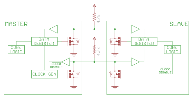
Figure 5: electrical connections for basic I2C communication (courtesy of Sparkfun).
As mentioned earlier, I2C is a two-wire protocol (plus ground!), a.k.a. a two-wire interface (TWI), that includes one data line (SDA) and one master-generated clock line (SCL). Thus we only have two pins to keep track of! So let’s dive into how to twiddle SCL and SDA to make Figures 1-4 happen!
Beginning Bit Banging
Alright then, let’s do this! I’ll try to make this as universal as possible, meaning that I’ll provide code examples in C for PIC and MSP430 microcontrollers. For PIC users I’m using the PICkit 3 with MPLAB X IDE v3.55; check out the Instructable Programming PIC Microcontrollers for initial setup of the project. For MSP430 users, I’m using msp430-gcc for compiling and mspdebug for flashing.
Initializing
Before executing any I2C transactions we’ll need to configure the microcontroller’s appropriate pins. Be sure to change the appropriate pin numbers and port names to those used in your project! For now just skim over the code; all will be revealed by the end of this post:
// Initializing I2C with PIC:
#include <xc.h>
#include <stdint.h>
#include <stdbool.h>

#define _XTAL_FREQ     8000000   // crystal frequency [Hz], needed for __delay_us()
#define SCL            (1 << 0)   // bit 0
#define SDA            (1 << 1)   // bit 1

#define I2C_ANSEL      ANSELC
#define I2C_INPORT     PORTC
#define I2C_TRIS       TRISC

#define I2C_SET_SCL    I2C_TRIS |= SCL;
#define I2C_CLR_SCL    I2C_TRIS &= ~SCL;
#define I2C_SET_SDA    I2C_TRIS |= SDA;
#define I2C_CLR_SDA    I2C_TRIS &= ~SDA;
#define I2C_DELAY      __delay_us(5);   // compiler-specific function: MPLAB X v3


void i2c_init(void)
{
    I2C_ANSEL &= ~( SCL | SDA );   // set as digital IO

    I2C_SET_SCL
    I2C_SET_SDA

    I2C_DELAY
}
// Initializing I2C with MSP430:
#include <stdbool.h>
#include <msp430g2553.h>

#define SCL            BIT0
#define SDA            BIT1

#define I2C_PSEL       P2SEL
#define I2C_P2SEL      P2SEL2
#define I2C_INPORT     P2IN
#define I2C_PDIR       P2DIR

#define I2C_SET_SCL    I2C_PDIR &= ~SCL;
#define I2C_CLR_SCL    I2C_PDIR |= SCL;
#define I2C_SET_SDA    I2C_PDIR &= ~SDA;
#define I2C_CLR_SDA    I2C_PDIR |= SDA;
#define I2C_DELAY      _delay_cycles(10);   // 5 microseconds at 8MHz

void i2c_init(void)
{
    I2C_PSEL &= ~( SCL | SDA );   // I/O enabled
    I2C_P2SEL &= ~( SCL | SDA );

    I2C_SET_SCL
    I2C_SET_SDA

    I2C_DELAY
}
Setting and Clearing Bits
The most basic operations we’ll need are setting (logical 1) and clearing (logical 0) bits. You may laugh, but due to the open-drain nature of I2C this isn’t wholly trivial. Instead of just outputting ones and zeros willy nilly, we’ll have to set the desired pin as an input when we want to set a bit. This may seem a bit bizarre, but when microcontrollers are set as inputs their pin states are set to high impedance, or open-drain. Then we’ll need to set the pin as an output to clear a bit.
Let’s take a look at how we set a bit in the init() sections above:
// Setting a bit with a PIC:
// ...
#define I2C_TRIS       TRISC

#define I2C_SET_SCL    I2C_PDIR &= ~SCL;
// ...
// Setting a bit with MSP430:
// ...
#define I2C_PDIR       P2DIR

#define I2C_SET_SCL    I2C_PDIR &= ~SCL;
// ...
And clearing a bit may look more familiar:
// Clearing a bit with a PIC:
#define I2C_CLR_SCL    I2C_TRIS &= ~SCL;
// Clearing a bit with MSP430:
#define I2C_CLR_SCL    I2C_PDIR |= SCL;
Not too tough, right? All we’re doing is specifying which port direction registers to twiddle our I2C pins on with the #define I2C_TRIS or #define I2C_PDIR. Then we’re setting the pin as an input (Hi-Z) to set it, or an output to clear it. Note that here we’re relying on the typical behavior of output pins defaulting to low (0V) states, hence our omission of setting the output low in our CLEAR_BIT functions. Make sure to verify that this is true à la your device’s datasheet!
Also notice that we’re doing something kind of funky: we’re defining functions in #define directives instead of ol’ fashioned declarations (e.g. void i2c_set_scl(void);). This technique uses the preprocessor to substitute code in wherever we call the #define functions at compile-time, saving precious memory on our microcontrollers and avoiding errors and readability sacrifices if we’d insert the code ourselves. I digress, but encourage the interested reader to investigate this topic further! Let’s move on.
Idling and Start/Stop Conditions
First, a quick definition: idle. An idle bus means that both SCL and SDA are high — this is the state of the bus when no transactions are taking place. Remember that lines on a bus being high (logical 1) means that no device is actively pulling a line low (logical 0).
When the bus is idle and the master now wants to initiate an I2C transaction, she begins with a start condition. Here, she pulls and holds down the SDA line (clear SDA), waits, then pulls and holds down SCL (clear SCL), and waits again. This signals to the slave that a transaction is about to take place on the bus. See Figure 6 for a visual representation.
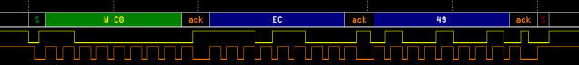
Figure 6: example I2C write transaction. The orange trace represents SCL, the yellow SDA, and the I2C interpretation rests on top.
To write a start condition function we’ll use our I2C_SET and I2C_CLR functions:
// Initiating an I2C start condition:
void i2c_start_condition( void )
{
    I2C_SET_SCL
    I2C_SET_SDA
    I2C_DELAY
    I2C_CLR_SDA
    I2C_DELAY
    I2C_CLR_SCL
    I2C_DELAY
}
Whoa, doesn’t really look like a C function, does it? (Where are all the semicolons?!) And why isn’t there a different function for PIC versus MSP430? Well, that’s the beauty of the preprocessor. We could even turn this function into a #define function (using backslashes for the newlines), but we’ll cover more optimization stuff in a later tutorial.
Stop conditions are sort of start conditions in reverse. The master pulls SDA low, waits, pulls SCL high, waits, pulls SDA high, and waits. Then we’re back in idle, ready for more I2C action!
// Initiating an I2C stop condition:
void i2c_stop_condition( void )
{
    I2C_CLR_SDA
    I2C_DELAY
    I2C_SET_SCL
    I2C_DELAY
    I2C_SET_SDA
    I2C_DELAY
}
Reading and Writing Bits
Masters and slaves always read bit values when SCL is high, so it’s the job of the writers to make sure SDA has a stable value for the entire duration of this state. To ensure this, the writer typically changes the SDA line immediately after SCL goes low so there’s plenty of time for the signal to stabilize. We can observe this in Figure 6, where SDA is pulled low immediately after the second SCL pulse so that its value is no doubt zero for the third clock pulse.
Let’s see the code for writing a bit:
// Writing a bit in I2C:
void i2c_write_bit( uint8_t b )
{
    if( b > 0 ) I2C_SET_SDA;
    else I2C_CLR_SDA;

    I2C_DELAY
    I2C_SET_SCL
    I2C_DELAY
    I2C_CLR_SCL
}
Let’s continue with reading a bit:
// Reading a bit in I2C:
uint8_t i2c_read_bit( void )
{
    uint8_t b;

    I2C_SET_SDA
    I2C_DELAY
    I2C_SET_SCL
    I2C_DELAY

    if( I2C_INPORT & SDA ) b = 1;
    else b = 0;

    I2C_CLR_SCL

    return b;
}
Allow me now to impose a stop condition! If you’re having a hard time following at this point: stop here, follow the functions with your finger, compare with Figure 6, and repeat. Make sure you’re up to speed before moving on, for the waves only get bigger.
Acknowledging or Not
But first, an easy discussion about acknowledging (ACKing). Recall that after every byte of data sent the other device with either ACK to say, ‘All is good, carry on,’ or NACK to express the opposite. A NACK can also occur if the master attempts to talk to a slave using an incorrect address, or if the device is simply non-responsive. Finally, a master will use a NACK to signal a slave to stop sending it data.
Writing a Byte
We’re now encroaching on full I2C transactions! Besides calling i2c_write_bit() eight times we can lump in other function calls that frequently precede or proceed sending a byte. We’ll include the options to precede with a start condition, proceed with a stop condition, and check whether the recipient ACKed.
But first, another discussion: endianness. Silly word. It refers to the order of bits and bytes sent. I2C uses big-endian bit order, so the most-significant bits are sent before the least-significant. It may have never crossed your mind, but the idea of endianness may save you in the future (e.g. SMBus, an I2C protocol, uses little-endian byte order, so least-significant bytes are sent first). Anyhoo, back to writing bytes:
// Writing a byte with I2C:
bool i2c_write_byte( uint8_t B,
                     bool start,
                     bool stop )
{
    uint8_t ack = 0;

    if( start ) i2c_start_condition();

    uint8_t i;
    for( i = 0; i < 8; i++ )
    {
        i2c_write_bit( B & 0x80 );   // write the most-significant bit
        B <<= 1;
    }

    ack = i2c_read_bit();

    if( stop ) i2c_stop_condition();

    return ack;
}
Reading a Byte
Hark back to Figure 3 above, and take a look at the example reading transaction in Figure 7:

Figure 7: example I2C read transaction. The orange trace represents SCL, the yellow SDA, and the I2C interpretation rests on top.
The second blue byte in Figure 7 is the only byte read by the master, which is why I reference Figure 3 as well to disambiguate the distinction. There isn’t quite as much going on compared with writing a byte, but we’ll borrow the stop condition option. And instead of checking for an ACK, we’ll include the option to ACK (‘send me more data!’) or not (‘no more, please!’). Oh, and of course we’ll be reading bits instead of writing:
// Reading a byte with I2C:
uint8_t i2c_read_byte( bool ack,
                       bool stop )
{
    uint8_t B = 0;

    uint8_t i;
    for( i = 0; i < 8; i++ )
    {
        B <<= 1;
        B |= i2c_read_bit();
    }

    if( ack ) i2c_write_bit(0);
    else i2c_write_bit(1);

    if( stop ) i2c_stop_condition();

    return B;
}
Reading and Writing I2C Data
Woohoo! We’ve made it to creating actual I2C transactions! We’ll begin, like always, with the simplest: i2c_read_byte() and i2c_write_byte().
I2C Send Byte and Receive Byte
For lack of better terms, I’ve chosen to call ‘sending’ and ‘receiving’ the acts of the master writing the slave address to the bus then writing to or reading from a slave. While the former has occasional utility, the latter is really only useful in debugging (unless the slave has only a single function that executes every time that it’s addressed). Nonetheless, neither are too difficult to concoct or analyze. Beginning with sending a byte:
// Sending a byte with I2C:
bool i2c_send_byte( uint8_t address,
                    uint8_t data )
{
    if( i2c_write_byte( address << 1, true, false ) )   // start, send address, write
    {
        // send data, stop
        if( i2c_write_byte( data, false, true ) )  return true;
    }

    i2c_stop_condition();   // make sure to impose a stop if NAK'd
    return false;
}
And reading a byte:
// Receiving a byte with a I2C:
uint8_t i2c_receive_byte( uint8_t address )
{
    if( i2c_write_byte( ( address << 1 ) | 0x01, true, false ) )   // start, send address, read
    {
        return i2c_read_byte( false, true );
    }

    return 0;   // return zero if NAK'd
}
Notice how, in the first i2c_write_byte() functions, we’re shifting the address by one bit and ANDing it with a 1 for i2c_receive_byte. That is because I2C addresses are 7 bits wide, and the least-significant bit we’re appending (notice it’s 0 for i2c_send_byte()) represent either a call to signify we’re going to write a byte, in the case of a 0, or we’d like to read some data for the 1 case.
I2C Send Byte Data and Receive Byte Data
Finally, we’ve arrived near the summit. These two functions will be the powerhouses of your I2C transactions. The extra ‘data’ means we’re sending an extra byte to the slave to tell it which register we’re interested in. For I2C writing a byte of data, this simply translates to sending one more byte than with i2c_send_byte():
// Sending a byte of data with I2C:
bool i2c_send_byte_data( uint8_t address,
                         uint8_t reg,
                         uint8_t data )
{
    if( i2c_write_byte( address << 1, true, false ) )   // start, send address, write
    {
        if( i2c_write_byte( reg, false, false ) )   // send desired register
        {
            if( i2c_write_byte( data, false, true ) ) return true;   // send data, stop
        }
    }

    i2c_stop_condition();
    return false;
}
Receiving a byte of data is more like extending i2c_send_byte() with i2c_receive_byte() immediately afterward. Now we could do just this, but I’m going to avoid using these previous functions in case we want to delete them (or just one) later:
// Receiving a byte of data with I2C:
uint8_t i2c_receive_byte_data( uint8_t address,
                               uint8_t reg )
{
    if( i2c_write_byte( address << 1, true, false ) )   // start, send address, write
    {
        if( i2c_write_byte( reg, false, false ) )   // send desired register
        {
            if( i2c_write_byte( ( address << 1) | 0x01, true, false ) )   // start again, send address, read
            {
                return i2c_read_byte( false, true );   // read data
            }
        }
    }

    i2c_stop_condition();
    return 0;   // return zero if NACKed
}
Timing
We’ve kicked this can down the road since the beginning, but now it’s time to talk timing. Per the latest I2C specification (April 2014), I2C bit rates range from 100 thousand bits per second (kbps) in Normal Mode to 400kbps in Fast Mode and up (3.4Mbps!). Remember, since I2C is synchronous we aren’t coerced into transmitting data at rigid baud rates. (However, some off-the-shelf devices include timeout functions while waiting for data so we’re not quite free to choose arbitrarily-low data rates whilst interfacing with these devices. Check the datasheet!) So what’s stopping us from transmitting at 0.05bps (3 bits per minute)? Well, let’s take a look at the I2C specification:
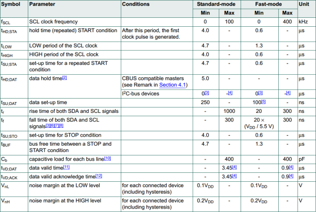
Figure 8: I2C timing specification table (adapted, courtesy of NXP).
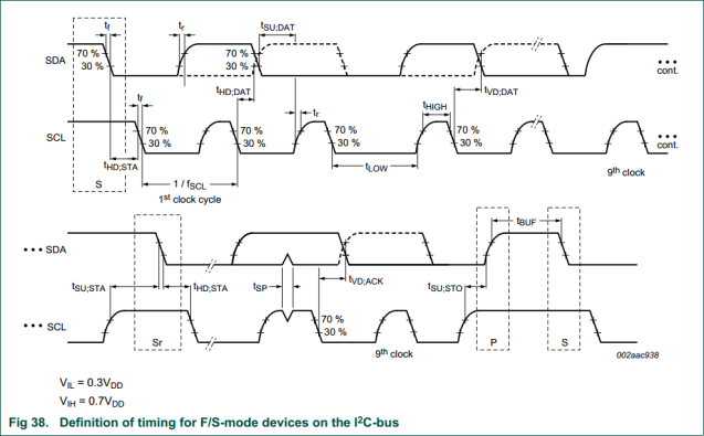
Figure 9: I2C timing specification figure (courtesy of NXP).
Notice there are a lot of hyphens in the ‘Max’ columns — this means there is no limit for that parameter. The only maximum times we need to be wary of are rise/fall times and data valid times. The formers are dictated by our microcontroller’s slew rate (typically less than a few hundred nanoseconds) and the bus capacitance (typically dominated by trace/wire length); the latter can be configured in software — since we change the SDA value immediately after a falling SCL edge these values are minimal (a few microcontroller instruction cycles). In short: we’re good. We can transmit as slow as we want!
Now for the upper end of data rates we must be wary of minimum on-times. Scroll between Figure 8 and Figure 9 and we can see that the maximum delay time we encounter is 5μs (data hold time). For simplicity we’ve set our I2C_DELAY function to this maximum delay time, though a few microseconds per transaction can be saved by defining several delay values. (But beware! Most delay functions take integers as arguments, so sending ‘4.7’ will be truncated as 4.)
Wrapping Up
Wait, what if we want to send TWO bytes of data? Or read two? Well, now it’s your turn! Look at Figures 2 and 4 and see if you can figure it out yourself.
In the next post in this series we’ll look at implementing these functions on a real device and get into troubleshooting techniques. But for now I’ll let you digest and celebrate — think of how far you’ve come! And how free you are! No more relying on dedicated hardware! And once you’ve done the grunt work you can reproduce this code forever! Your grandchildren can inherit your bit-banged I2C libraries! Joy!
For more tutorials and explanations of I2C, check out Sparkfun and tronixstuff. For more advanced characteristics and operation, including some gnarly troubleshooting techniques, see the I2C Bus homepage.

Aren’t there some missing lines of code? i2c_send_byte lacks a return value and bool stop is not used in the body of i2c_write_byte.
LikeLike
Good catch! Also some of the functions were misspelled (i2c_start_cond instead of i2c_start_condition). Should be good to go now. WordPress doesn’t make it easy to post code (if you’re a cheapo like me who doesn’t want to pay) so it’s been a cluster in this post. Thanks for paying attention!
LikeLike
Pingback: I2C Bit-Banging Tutorial: Part II | Calvin's Plot on the Interwebs
I’m having some issues with the i2c_read_bit expression. I’m not able to compile on a msp430g2553 due to issues with line “if( ( I2C_INPORT & I2C_SDA ) > 0 ) b = 1;”. The error is “The expression must be a modifiable lvalue”.
LikeLiked by 1 person
Yarr, try changing I2C_SDA to just SDA. I was a bit inconsistent there — I’ll search for more of those errors and update. Thanks for noticing!
LikeLiked by 1 person
I’m still getting the error that @ste123 has described. Help me with this please. @calcium300
LikeLike
Gorgeous! I’m adapting your code for an Arm Cortex-M0 MCU and it does work! The only problem I have it seems to reverse the bits of the result sent by the slave, an accelerometer in my case.
What if I want to specify a 16 bit address? I need to talk to an EEPROM on the very same bus
LikeLike
This made me think “Oh God I’m so stupid”:
#define SCL (1 << 0) // bit 0
#define SDA (1 << 1) // bit 1
So I guess you are declaring SCL as RC0 and SDA as RC1?
Or am I reading this completely wrong?
LikeLike
My previous comment got deleted.
I’m kind of beginner so forgive me for asking this
#define SCL (1 << 0) // bit 0
#define SDA (1 << 1) // bit 1
You are defining pin 1 and 2 of prot C as SCL and SDA?
This is the error
"Let’s take a look at how we set a bit in the init() sections above:
// Setting a bit with a PIC:
// …
#define I2C_TRIS TRISC
#define I2C_SET_SCL I2C_PDIR &= ~SCL;
// …"
#define I2C_SET_SCL I2C_PDIR &= ~SCL; is not for pic
this is for pic
#define I2C_SET_SCL I2C_TRIS |= SCL;
or did I get it wrong?
LikeLike
Hey good catch! A couple things: 1) It’s stupidly difficult to post code on here by using vanilla (i.e. free, app-less) means, so the code here may have errors; 2) I revamped a lot of this code from when it was initially published, and I didn’t get around to testing it all (a big no-no, I know!); and 3) I have been a bit busy with life events lately to get around to testing all of the code.
Please see my Github repo (linked in Downloads) for more up-to-date code, which may have fixed this error already. And I know it sounds like a cop-out, but finding errors like this is a great learning experience — keep on it!
LikeLike
Such a good article!!! keep posting such type of article……!!!! It helps me to develope my own Software based i2c communication system…….Thanks!!
LikeLike
Realy a good article, but should the ack not be inverted? In the i2c_write_byte function I would expect to be inverted
LikeLike
Incredibly useful. Thank you! I adapted this for STM32 MCU’s: https://github.com/PascalPolygon/stm32_bitbang_i2c
LikeLike
The last line of i2c_write_byte function is certainly in error. It says ” return ack;”, but it should return ack inverted, because an ack in i2c is a hardware low state.
There’s more than one way to do it, but i used “if (ack) return 0; else return 1;”
LikeLike